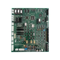

1. Fundamental Principles of VVVF Control
1.1 The V/Hz Relationship
The core principle of VVVF control is maintaining a constant ratio between motor voltage (V) and frequency (Hz). In an AC induction motor, the magnetic flux in the stator is proportional to V/f. If frequency is reduced without proportionally reducing voltage, the magnetic core saturates, causing excessive current and overheating. Conversely, if voltage is too low for the frequency, torque production drops off.
By maintaining V/f constant across the speed range, the VVVF drive ensures that the motor produces rated torque from zero speed up to base speed. Above base speed, voltage cannot increase beyond the mains supply, so the drive enters "field weakening" mode, where frequency increases while voltage remains constant. In this region, maximum torque decreases with speed, but the motor can continue accelerating to its maximum rated speed.
1.2 Power Stage Architecture
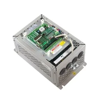
A typical elevator VVVF drive consists of three power conversion stages:
Rectifier: Converts three-phase AC mains power (typically 380-480V, 50/60 Hz) into DC. Modern drives use active front-end (AFE) rectifiers with IGBT bridges that draw sinusoidal current from the mains with power factor approaching unity, rather than the older diode bridge designs that introduced harmonic distortion.
DC Bus: A DC link capacitor bank smooths the rectified DC and stores energy for the inverter stage. Typical DC bus voltage is 600-700V for 400V-class drives. The capacitors also absorb regenerated energy during braking.
Inverter: Uses pulse-width modulation (PWM) to convert DC back into variable-frequency AC. Six IGBTs (Insulated Gate Bipolar Transistors) arranged in a three-phase bridge switch at frequencies of 2-16 kHz, producing a synthesized sine wave output whose voltage and frequency are precisely controlled by the drive's processor.

2. Control Algorithms and Performance
2.1 Scalar (V/f) Control
The simplest VVVF implementation uses open-loop V/f control, where the drive commands a specific voltage and frequency based on a speed reference signal, without measuring actual motor speed or current. This approach is cost-effective and adequate for simple applications such as freight elevators and low-speed passenger lifts. However, it cannot maintain precise speed under varying load conditions and offers limited torque at low speeds.
2.2 Vector Control (Field-Oriented Control)
Modern passenger elevators universally employ vector control, also known as field-oriented control (FOC). This algorithm transforms the three-phase motor currents into a rotating reference frame aligned with the rotor flux, allowing independent control of torque-producing current and flux-producing current - analogous to the separate armature and field control of a DC motor.
Vector control requires feedback of rotor position or flux angle, obtained either from an encoder mounted on the motor shaft (sensored vector control) or estimated from motor voltage and current measurements (sensorless vector control). High-speed elevators (>3 m/s) invariably use encoders with resolutions of 1,000-4,096 pulses per revolution for precise speed and position control.
Performance comparison: Vector-controlled elevators achieve speed regulation accuracy of ±0.1% and position accuracy within ±3 mm at landing - a 10-fold improvement over older V/f drives and a 50-fold improvement over two-speed motor systems.
2.3 Direct Torque Control (DTC)
An advanced control strategy used in premium elevator drives, DTC directly controls motor torque and flux without intermediate current control loops. By comparing actual motor states to a mathematical model, the DTC controller selects the optimal inverter switching state every 25-40 microseconds. This provides exceptionally fast torque response (< 2 ms) and superior low-speed performance, making DTC ideal for high-rise elevators with heavy loads and critical leveling requirements.
3. Elevator Motion Profiling
The VVVF drive executes a predefined motion profile for each trip, calculated by the elevator controller based on travel distance, rated speed, and comfort parameters. A typical profile consists of:
Acceleration phase: Jerk-limited ramp from 0 to rated speed. Maximum jerk is typically 0.5-2.0 m/s³, with higher values acceptable for freight and lower values for luxury passenger elevators.
Constant speed phase: Steady travel at rated speed for the majority of the trip distance.
Deceleration phase: Symmetric to acceleration, bringing the car smoothly to creep speed (typically 0.1-0.3 m/s) before entering the landing zone.
Leveling: Precise low-speed approach to align the car floor with the landing sill within ±5 mm.
The VVVF drive receives a speed reference signal from the elevator controller (typically via analog 0-10V, ±10V, or digital CANopen/Ethernet communication) and uses its vector control algorithm to make the motor track this reference as closely as possible. Modern drives achieve speed following errors of less than 0.5% during constant speed and less than 2% during acceleration.
4. Regenerative Drive Technology
4.1 Energy Recovery Principle
In a conventional (non-regenerative) VVVF drive, when the elevator descends with a light car or ascends with a heavy car, the motor acts as a generator, producing electrical energy. Without regeneration, this energy is dissipated as heat in braking resistors connected to the DC bus. A typical non-regenerative drive may waste 20-40% of its total energy consumption as resistor heat.
Regenerative drives replace the diode rectifier with an active IGBT front end that can transfer energy bidirectionally. When the motor generates power, the regenerative converter synchronizes with the mains and feeds energy back into the building's electrical grid. The efficiency improvement is substantial:
| Building Type / Traffic | Energy Savings with Regeneration |
|---|---|
| Low-rise residential (light traffic) | 15 – 25% |
| Mid-rise office (moderate traffic) | 25 – 35% |
| High-rise commercial (heavy traffic) | 30 – 45% |
| Hospital or hotel (variable load) | 20 – 30% |
4.2 Active Front End (AFE) Advantages
Beyond energy recovery, AFE regenerative drives offer additional benefits:
Harmonic reduction: AFE drives draw nearly sinusoidal current with total harmonic distortion (THD) below 5%, compared to 80-120% THD from diode rectifiers. This eliminates the need for external harmonic filters and prevents interference with building electrical systems.
Unity power factor: AFE controls the phase angle between voltage and current, maintaining power factor near 1.0 across all operating conditions. This reduces utility demand charges and eliminates reactive power penalties.
Reduced machine room cooling: Elimination of braking resistors removes a significant heat source, reducing HVAC requirements for the machine room by 30-50%.
5. Drive Selection and Sizing
Selecting the correct VVVF drive for an elevator application requires matching drive capacity to motor requirements while considering overload capability, environmental conditions, and control features.
5.1 Power Rating
Drive continuous power rating must equal or exceed the motor's rated power. However, elevator applications require high overload capability for acceleration. The drive must deliver 150-200% of rated current for 10-60 seconds during acceleration from a standing start. Most elevator-specific drives are rated with a 150% overload for 60 seconds as standard.
5.2 Input Voltage and Phases
Standard industrial VVVF drives accept three-phase 380-480V AC input. For locations with only single-phase supply, specialized single-phase input drives are available up to approximately 3.7 kW. For very large elevators (heavy freight, high-speed), medium-voltage drives (690V or higher) may be specified to reduce current and cable size.
5.3 Enclosure and Environmental Rating
Machine room ambient temperature typically ranges from 5°C to 40°C. Drives must be derated above 40°C or provided with forced ventilation. For outdoor or unconditioned installations, specify drives with operating temperature ranges of -10°C to +50°C. Dusty environments require IP54 or higher enclosure ratings.
6. Maintenance and Diagnostics
6.1 Preventive Maintenance
VVVF drives require minimal maintenance compared to electromechanical control systems, but several items should be checked annually:
DC bus capacitors: Measure capacitance and compare to nameplate value. Capacitance loss > 20% indicates replacement is needed (typical life: 8-12 years).
Cooling system: Clean heatsink fins and cooling fans. Fan bearing life is typically 5-7 years; replace proactively.
Connections: Torque-check power terminal screws and inspect for discoloration from overheating.
Parameter backup: Download and archive drive parameters. Store backup in cloud or secure location for disaster recovery.
6.2 Built-in Diagnostics
Modern elevator VVVF drives include comprehensive diagnostic capabilities:
Real-time monitoring of motor current, voltage, torque, and temperature
Trip history logging with time stamps and operating conditions at fault
IGBT health monitoring (Vce saturation voltage trends)
Encoder feedback verification
Brake circuit monitoring
Many drives now offer IoT connectivity, uploading operational data to cloud platforms where AI algorithms analyze trends and predict failures before they occur. Early adopters report 30-50% reduction in unplanned downtime using predictive maintenance based on drive data analytics.
7. Future Trends
The evolution of VVVF elevator drives continues along several paths. Silicon carbide (SiC) IGBTs and MOSFETs enable switching frequencies above 50 kHz, reducing motor noise and allowing more compact filter designs. AI-based control algorithms that learn building traffic patterns and optimize dispatching in real-time are entering commercial deployment. And DC microgrid integration - where elevators connect directly to building-scale battery storage without AC conversion losses - promises another step-change in efficiency for net-zero buildings.