
1. Speed Governor (Overspeed Governor)
1.1 Working Principle
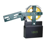
The speed governor is the triggering element of the elevator safety system. It continuously monitors car speed through a mechanical linkage: a governor rope passes around a sheave in the governor housing (typically located in the machine room or shaft overhead) and is anchored at the car safety gear. As the car moves, the governor rope rotates the governor sheave at a speed proportional to car velocity.
Inside the governor, a centrifugal mechanism monitors sheave speed. When the car speed exceeds a predetermined tripping velocity - typically 115% of rated speed for upward overspeed and 115-140% for downward overspeed depending on code requirements - centrifugal flyweights or a cam mechanism actuates a switch and mechanically grips the governor rope. This action simultaneously:
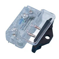
Cuts power to the motor and brake via an electrical safety switch
Grips the governor rope, creating tension that pulls the safety gear activation linkage
1.2 Types of Speed Governors
| Governor Type | Tripping Mechanism | Speed Range | Typical Application |
|---|---|---|---|
| Centrifugal (Flyweight) | Spring-opposed flyweights | 0.5 – 4.0 m/s | Standard passenger and freight |
| Centrifugal (Cam) | Cam profile + roller | 0.3 – 2.5 m/s | Low-speed, cost-sensitive |
| Electronic | Encoder + processor | 0.5 – 10+ m/s | High-speed, MRL elevators |
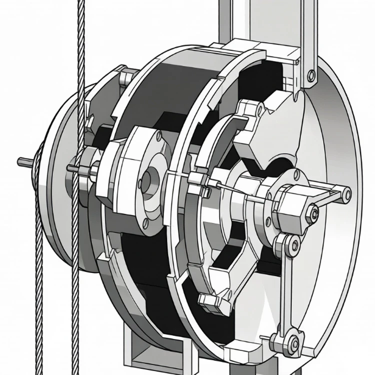
Electronic governors are increasingly common in high-speed and MRL installations. They use a shaft encoder on the governor sheave and a dedicated processor to calculate velocity and acceleration. The advantage is precise calibration and the ability to monitor jerk (rate of acceleration change), which mechanical governors cannot detect. However, electronic governors require redundant systems to meet safety integrity level (SIL) requirements.
1.3 Calibration and Testing
Speed governor tripping speed must be verified during initial installation and at regular intervals. EN 81-20 requires governor testing at least every 12 months for passenger elevators and every 6 months for freight elevators with heavy duty cycles. The test involves rotating the governor sheave at gradually increasing speed while measuring the exact tripping point. Tripping speed tolerance is typically ±3% of the rated tripping speed.
Critical detail: The governor rope is a separate safety component from the main suspension ropes. It must be inspected for wear, corrosion, and proper tension at each maintenance visit. Rope replacement is typically required after 5-7 years or when diameter reduction exceeds 5%.
2. Safety Gear
2.1 Working Principle
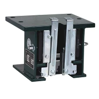
The safety gear is the braking device that physically arrests the car if it descends at excessive speed. When the speed governor trips, the tensioned governor rope pulls a wedge or roller mechanism in the safety gear, forcing braking elements against the guide rails. The resulting friction converts the car's kinetic energy into heat, bringing the car to a controlled stop.
Modern elevators exclusively use progressive safety gears, which apply braking force gradually rather than instantaneously. This prevents the dangerous deceleration spikes (up to 10 g) associated with older instantaneous safety gears. Progressive safety gears limit deceleration to a maximum of 1 g (9.81 m/s²) for passenger elevators, ensuring occupant safety during an emergency stop.
2.2 Safety Gear Types
| Type | Braking Element | Force Application | Max Speed |
|---|---|---|---|
| Wedge-type (Instantaneous) | Hardened steel wedges | Spring-assisted mechanical | ≤ 0.63 m/s (legacy only) |
| Eccentric roller (Progressive) | Eccentric rollers + springs | Spring-loaded, self-energizing | Up to 3.0 m/s |
| Wedge-type (Progressive) | Spring-opposed wedges | Hydraulic damping + springs | Up to 10.0 m/s |
| Multiple wedge (High-speed) | Distributed wedge array | Hydraulic or spring | Up to 10.0+ m/s |
2.3 Safety Gear Testing
EN 81-20 mandates a full safety gear test with rated load at tripping speed during type certification. In the field, annual tests are required with empty car (or minimum load per local codes) to verify that the safety gear grips the rails and brings the car to a stop. After testing, the guide rails must be inspected for deformation or scoring at the safety gear contact points, and the safety gear must be dismantled and inspected for wear.
The test procedure involves:
Verify governor tripping speed before the safety gear test
Run the car downward at inspection speed
Trigger the governor manually or by overspeeding
Measure stopping distance and deceleration rate
Inspect guide rails and safety gear components for damage
Reset the safety gear and verify normal operation
3. Buffers
3.1 Function and Requirements
Buffers are the final safety device, installed in the elevator pit to cushion the impact of the car or counterweight if it overtravels beyond the terminal landing. Buffers must absorb the kinetic energy of a fully loaded car descending at 115% of rated speed, or a counterweight at its maximum possible speed, without causing deceleration exceeding 1 g.
Buffer requirements are specified in EN 81-20/50 Section 5.5 and ASME A17.1 Section 2.22. Key parameters include:
Stroke length: Must be sufficient to absorb the impact energy. For energy accumulation buffers, stroke is typically 65-400 mm depending on rated speed. For energy dissipation buffers, stroke ranges from 150-1500 mm.
Return to extended position: After compression, the buffer must return to its full height within 120 seconds (energy dissipation type).
Corrosion resistance: Buffer components exposed to the pit environment must resist corrosion from moisture, cleaning chemicals, and hydraulic oil.
3.2 Buffer Types
| Buffer Type | Principle | Speed Limit | Stroke Range | Maintenance |
|---|---|---|---|---|
| Spring (Energy Accumulation) | Steel spring compression | ≤ 1.0 m/s | 65 – 210 mm | Inspect for corrosion and cracking |
| Polyurethane (Energy Accumulation) | Elastomeric compression | ≤ 1.0 m/s | 80 – 250 mm | Replace when compression set > 15% |
| Hydraulic (Energy Dissipation) | Oil forced through orifices | No limit | 150 – 1500 mm | Oil level, seal condition, rust |
3.3 Hydraulic Buffer Details
Hydraulic buffers are required for elevators traveling above 1.0 m/s. They consist of a cylinder filled with hydraulic oil and a piston that compresses the oil through calibrated orifices during impact. The orifice design creates a velocity-dependent damping force: high initial speed meets high resistance, while the final portion of the stroke provides gentle deceleration.
The return mechanism is critical. After compression, a return spring and one-way valve allow the buffer to extend automatically, preparing it for the next impact. If the buffer fails to return within 120 seconds, a safety switch (buffer switch) prevents normal elevator operation until the buffer is restored.
Hydraulic buffer maintenance includes:
Quarterly inspection of oil level and leakage
Annual test of buffer compression and return function
Replacement of oil every 5-7 years or when contamination is detected
Inspection of the buffer switch for proper adjustment and electrical continuity
4. Safety Chain and Redundancy
The three safety devices - governor, safety gear, and buffers - operate sequentially in a safety chain. The governor detects the fault and triggers the safety gear, which arrests the car. If the safety gear fails or the overtravel is extreme, the buffers provide final protection. Additionally, modern elevators include redundant electrical safety circuits that cut power to the drive and brake if any safety device is activated.
Per EN 81-20, the safety chain must be hardwired (not software-dependent) for critical functions, and the safety circuit must use positively driven contacts that cannot fail in a closed position. This hardware-level redundancy ensures that even a complete control system failure cannot bypass the mechanical safety devices.