
1. Function and Load Characteristics
Guide rails serve three primary functions in an elevator system. First, they provide the running surface for guide shoes or rollers attached to the car and counterweight frames, ensuring smooth vertical travel with minimal lateral movement. Second, they serve as the reaction surface for the safety gear during an emergency stop, requiring sufficient strength to withstand the enormous forces generated by a fully loaded car arresting in free fall. Third, they transfer operational loads - including car imbalance, wind pressure in high-rise applications, and dynamic forces from acceleration - to the building structure.
The forces imposed on guide rails vary dramatically based on application. A low-speed freight elevator in a warehouse may impose minimal lateral loads, while a high-rise passenger elevator traveling at 6 m/s in a building exposed to wind loads of 200 km/h generates significant guide rail deflection and wear. Understanding these load characteristics is essential for proper rail specification.
2. Guide Rail Types and Cross-Sections
2.1 Machined Guide Rails (T-Type Solid Rails)
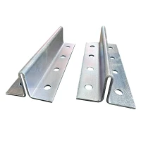
The most common guide rail type worldwide is the machined T-rail, named for its cross-sectional shape resembling an inverted "T." The guiding surface is machined from solid steel, providing excellent wear resistance and load-bearing capacity. Standard sizes range from T45/A (45 mm head width) for light-duty applications to T140/B (140 mm head width) for heavy freight and high-speed elevators.
| Rail Size | Head Width (mm) | Base Width (mm) | Height (mm) | Typical Application |
|---|---|---|---|---|
| T45/A | 45 | 45 | 45 | Residential, light-duty passenger |
| T50/A | 50 | 50 | 50 | Standard commercial passenger |
| T70-1/B | 70 | 65 | 65 | Heavy-duty commercial, hospital |
| T90/B | 90 | 75 | 78 | Freight, high-speed applications |
| T114/B | 114 | 89 | 89 | Heavy freight, mine elevators |
| T140-1/B | 140 | 114 | 114 | Ultra-heavy duty, special applications |

T-rails are manufactured from cold-drawn or hot-rolled steel, with the guiding surface subsequently machined to achieve the required surface finish and dimensional tolerances. Per EN 81-20, the guiding surface roughness must not exceed Ra 6.3 μm, and straightness tolerance is typically 0.5 mm per 5 meters of rail length.
2.2 Hollow Guide Rails
Hollow guide rails offer a cost-effective alternative for applications where load requirements are moderate. These rails are formed from steel sheet into a rectangular hollow section with one machined guiding surface. Common sizes include TK3A, TK5A, and TK5, with "T" indicating "thin" and "K" indicating "cold-formed."
While hollow rails offer weight savings of 30-40% compared to solid T-rails of equivalent size, they have lower rigidity and are not suitable for safety gear applications without an additional backing plate. Their primary advantage lies in counterweight guide applications and light-duty car guides where cost sensitivity is high.
2.3 Cold-Drawn Rails
Cold-drawn guide rails are produced by pulling steel through a die, resulting in improved surface hardness and dimensional accuracy compared to hot-rolled products. The cold-working process increases yield strength by 15-25% and achieves surface roughness as fine as Ra 1.6 μm, reducing guide shoe wear and improving ride quality. Cold-drawn rails are increasingly specified for high-speed elevators where vibration and noise must be minimized.
2.4 Fishplates and Brackets
Individual rail sections are joined using fishplates - machined steel plates bolted across rail joints. Fishplates must maintain alignment within 0.05 mm across the joint to prevent guide shoe impact and noise. Rail brackets secure the rails to the shaft wall at intervals of 2.0-2.5 meters, with adjustable designs allowing fine-tuning of rail position during installation.
3. Manufacturing Standards and Quality Control
Guide rail quality is governed by multiple international standards:
EN 81-20/50 (Europe): Specifies dimensional tolerances, surface finish, material properties, and safety requirements for elevator guide rails.
ISO 7465: Defines dimensions and tolerances for T-type guide rails and their fishplates.
JIS A 4306 (Japan): Japanese Industrial Standard for elevator guide rails with specific requirements for high-speed applications.
GB/T 22562 (China): Chinese national standard equivalent to ISO 7465, widely used by global elevator component suppliers.
Key quality parameters include:
| Parameter | Requirement | Inspection Method |
|---|---|---|
| Yield Strength | ≥ 370 MPa (for standard rails) | Tensile test per ISO 6892 |
| Surface Hardness | HB 140-220 | Brinell hardness test |
| Straightness | ≤ 0.5 mm / 5 m | Optical straightedge or laser |
| Surface Roughness (Ra) | ≤ 6.3 μm (≤ 3.2 μm for cold-drawn) | Profilometer |
| Guiding Surface Flatness | ≤ 0.05 mm / m | Precision straightedge + feeler gauge |
4. Installation Best Practices
4.1 Shaft Preparation
Before rail installation, verify shaft dimensions against architectural drawings. Shaft plumb must be within 20 mm over the full travel for standard applications, or 10 mm for high-speed installations. Mark bracket positions at the specified vertical spacing, accounting for any structural offsets or shaft irregularities.
4.2 Rail Alignment Procedure
Modern rail installation uses laser alignment systems to achieve the required precision. The process proceeds as follows:
Establish reference lines: Mount a laser transmitter at the top and bottom of the shaft, projecting a vertical reference plane for car and counterweight rails.
Install bottom brackets first: Secure the lowest bracket for each rail, setting it to the exact offset from the shaft wall specified in the layout drawing.
Build upward section by section: Install rail sections sequentially, checking alignment at each bracket. Use adjustable brackets to correct any deviation from the laser reference.
Verify joint alignment: At each fishplate joint, verify that the guiding surface is continuous within 0.05 mm. Use a precision straightedge spanning the joint.
Final survey: After complete installation, survey the full rail length with the laser system, documenting alignment data for the handover package.
Critical tolerance: For elevators operating above 2.5 m/s, EN 81-20 requires guide rail alignment within 1.5 mm over any 5-meter section. Deviations beyond this threshold cause guide shoe binding, excessive noise, and accelerated wear.
4.3 Lubrication and Corrosion Protection
Guide rails arrive from the factory with a protective oil coating that prevents corrosion during transport and storage. This coating should not be completely removed before installation, as it provides initial lubrication for guide shoe break-in. After installation, apply a thin film of rail lubricant (typically lithium-based grease or synthetic oil) to the guiding surfaces.
For outdoor elevators, coastal installations, or applications with high humidity, specify galvanized or stainless steel rails. Alternatively, apply a corrosion-resistant coating after installation and establish a quarterly inspection schedule for coating integrity.
5. Wear and Replacement Criteria
Guide rails wear primarily through abrasion from guide shoes. The wear rate depends on:
Travel distance and frequency (daily cycles)
Guide shoe material (nylon, polyurethane, or cast iron)
Lubrication quality and frequency
Alignment accuracy (misalignment concentrates wear)
Car loading (overloaded cars increase lateral forces)
Replacement criteria vary by application, but general guidelines are:
| Wear Indicator | Limit | Action |
|---|---|---|
| Guiding surface width reduction | > 10% of nominal width | Replace rail section |
| Local pitting or scoring depth | > 0.5 mm | Grind and polish, or replace |
| Edge deformation from safety gear engagement | Any visible deformation | Replace immediately |
| Corrosion pitting on guiding surface | > 0.2 mm depth or > 5% area | Replace or re-machine |
6. Emerging Trends
The guide rail industry is evolving in several directions. Composite guide rails incorporating carbon fiber reinforcement are under development for ultra-high-rise applications where steel weight becomes prohibitive. Rail-integrated vibration damping systems - where elastomeric layers are bonded between the rail and bracket - are gaining adoption for high-speed installations where ride quality is critical. Additionally, laser-hardened guiding surfaces that increase wear resistance by 300% without additional material are entering commercial production.