
1. Working Principle of the Door Operator
At its core, an elevator door operator is an electromechanical system that converts electrical energy into precise linear motion to open and close elevator doors. Modern door operators utilize a closed-loop control system consisting of a motor, controller, position feedback device, and mechanical transmission assembly.
The door opening process begins when the elevator control system sends a door-open signal upon car arrival at a landing. The door controller activates the motor, which drives the door panels through a mechanical transmission (typically a timing belt or toothed rack system). As the doors open, a position encoder continuously reports the door panel position to the controller, enabling smooth acceleration, constant-speed travel, and controlled deceleration.
Key specification: Modern door operators typically achieve opening speeds of 0.4-0.8 m/s, with opening time ranging from 2.5 to 4.0 seconds depending on door width and control parameters.
Door closing follows a similar sequence but with an added safety layer. An infrared light curtain or safety edge sensor monitors the door threshold throughout the closing cycle. If an obstruction is detected, the controller immediately reverses the door motion or holds the doors open. This safety function must comply with EN 81-20/50 requirements, which mandate that door reversal occurs within 50 milliseconds of obstruction detection.
2. Key Components
2.1 Door Motor
The door motor is the prime mover of the door operator. Contemporary systems predominantly use permanent magnet synchronous motors (PMSM) or brushless DC (BLDC) motors. These motors offer high torque density, precise speed control, and maintenance-free operation compared to traditional AC induction motors.
| Motor Type | Torque Range | Speed Range | Typical Application |
|---|---|---|---|
| AC Induction | 2-6 Nm | 0-1500 rpm | Legacy systems, cost-sensitive markets |
| BLDC | 1.5-8 Nm | 0-3000 rpm | Mid-range commercial elevators |
| PMSM | 2-10 Nm | 0-4000 rpm | High-speed, premium applications |
2.2 Transmission System
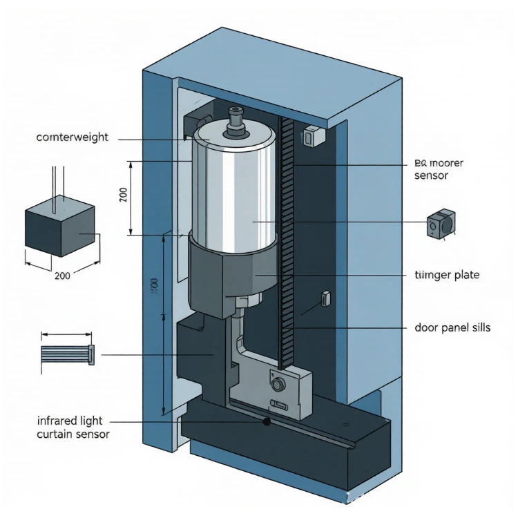
The transmission system transfers rotational motion from the motor to the linear movement of door panels. The most common configurations are:
Timing Belt Drive: A toothed belt connects a motor pulley to a driven pulley, with door hangers attached to the belt via clamps. This system offers quiet operation, low backlash, and easy maintenance. Belt pitch is typically 5 mm or 8 mm.
Rack and Pinion: A pinion gear on the motor shaft engages with a linear rack attached to the door panel. This provides robust force transmission but requires periodic lubrication.
Direct Drive (Linear Motor): Emerging technology where the motor's stator is integrated into the door track, eliminating mechanical transmission altogether. This offers the highest precision and lowest noise but at significantly higher cost.
2.3 Door Controller
The door controller is the electronic brain of the door operator. It receives signals from the elevator main controller, processes encoder feedback, and generates motor drive signals. Modern controllers use vector control algorithms to achieve smooth door motion profiles with jerk-limited acceleration curves. The controller also handles diagnostic functions, storing fault codes and operational statistics for maintenance access.
2.4 Position Encoder
A rotary encoder mounted on the motor shaft or belt pulley provides position and velocity feedback. Incremental encoders with resolutions of 500-2000 pulses per revolution (PPR) are standard, while high-end systems may use absolute encoders to eliminate homing requirements after power cycles.
2.5 Safety Sensors
Door safety sensors prevent the doors from closing on passengers or objects. The two primary types are:
Infrared Light Curtains: Arrays of infrared LED transmitters and receivers create an invisible detection grid across the door opening. Coverage typically spans the full door width from 20 mm above floor level to 1800 mm height.
Mechanical Safety Edges: Rubber profiles with embedded pressure-sensitive switches mounted on the door leading edge. These serve as a secondary safety device, activating upon physical contact.
3. Common Failures and Troubleshooting
3.1 Excessive Door Closing Force
When doors require unusually high force to close, the root cause is typically one of:
Mechanical obstruction in the door track or sill
Worn or damaged door rollers causing increased friction
Misaligned door panels (vane clearance out of specification)
Incorrect force/torque limit settings in the controller
Resolution: Clean and inspect the door track, check roller condition and replace if flat-spotted, verify door panel alignment (typical vane clearance: 2-4 mm), and recalibrate the closing force to comply with EN 81-20 limits (maximum 150 N closing force at the leading edge).
3.2 Erratic Door Motion or Hunting
Doors that oscillate, overshoot, or exhibit inconsistent speeds point to control system issues:
Encoder feedback failure or degraded signal quality
Loose connections in motor power or feedback cables
Controller parameters drifted from factory settings
Mechanical backlash in the transmission system
Resolution: Inspect encoder wiring and connectors with an oscilloscope; verify encoder supply voltage (typically 5V or 24V DC). Re-download factory motion parameters if available. Check belt tension (typically 20-30 N deflection force at mid-span) and inspect rack-and-pinion backlash.
3.3 Failure to Open or Close
Complete failure of door motion is the most critical fault, often caused by:
Controller power supply failure (check 24V/48V/110V input)
Motor winding failure (measure winding resistance and insulation)
Mechanical jam (debris in track, seized rollers, or impact damage)
Door lock circuit fault preventing motion enable
Resolution: Follow a systematic diagnostic sequence: verify controller power supply voltages, test motor windings (expect 1-10 ohms for most door motors), perform manual door movement test to rule out mechanical seizure, and verify door lock switch continuity.
3.4 Premature Belt Wear
Timing belts typically last 5-8 years but may fail earlier due to:
Incorrect tension (too tight causes fiber fatigue; too loose causes tooth jumping)
Contamination (oil, dust, or debris accelerating rubber degradation)
Pulley misalignment (causing uneven tooth loading)
Excessive heat from motor or brake
Resolution: Set belt tension to manufacturer specification (typically 2-3% elongation under specified test force). Install belt guards to prevent contamination. Check pulley alignment with a straight edge (should be within 0.5 mm/m). Ensure motor cooling is adequate.
4. Maintenance Best Practices
Preventive maintenance extends door operator lifespan and reduces callbacks. Recommended intervals:
| Task | Monthly | Quarterly | Annually |
|---|---|---|---|
| Clean door track and sill | ✓ | ||
| Inspect rollers and hangers | ✓ | ||
| Check belt tension and condition | ✓ | ||
| Test safety sensor function | ✓ | ||
| Verify door closing force | ✓ | ||
| Lubricate rack/pinion (if equipped) | ✓ | ||
| Full controller diagnostic scan | ✓ |
Pro tip: Track door cycle counts using the controller's built-in statistics function. Most door operators are rated for 5-10 million cycles. When approaching rated life, plan proactive replacement of wear components (belts, rollers, and bearings) to prevent in-service failures.
5. Selecting Replacement Door Operator Parts
When sourcing replacement door operator components for maintenance or modernization, verify compatibility across:
Door width and weight: Ensure the operator's torque and speed specifications match your door panels.
Controller protocol: The new operator must communicate with the existing elevator control system (common protocols include CANopen, Modbus, or proprietary serial).
Safety standards: Replacement operators in the EU must carry CE marking to EN 81-20/50; in North America, compliance with ASME A17.1 is required.
Environmental rating: For outdoor or harsh environments, specify IP54 or higher enclosure ratings.