
Elevator Safety Gear Types Progressive vs Instantaneous: Which One to Choose?
The selection between elevator safety gear types progressive vs instantaneous is a fundamental engineering decision that directly impacts passenger comfort and stopping performance during an overspeed event. Both types are designed to grip the guide rails and bring the car to a controlled stop, but their mechanical action and application suitability differ significantly.
Mechanical Design Differences Between Progressive and Instantaneous Gears
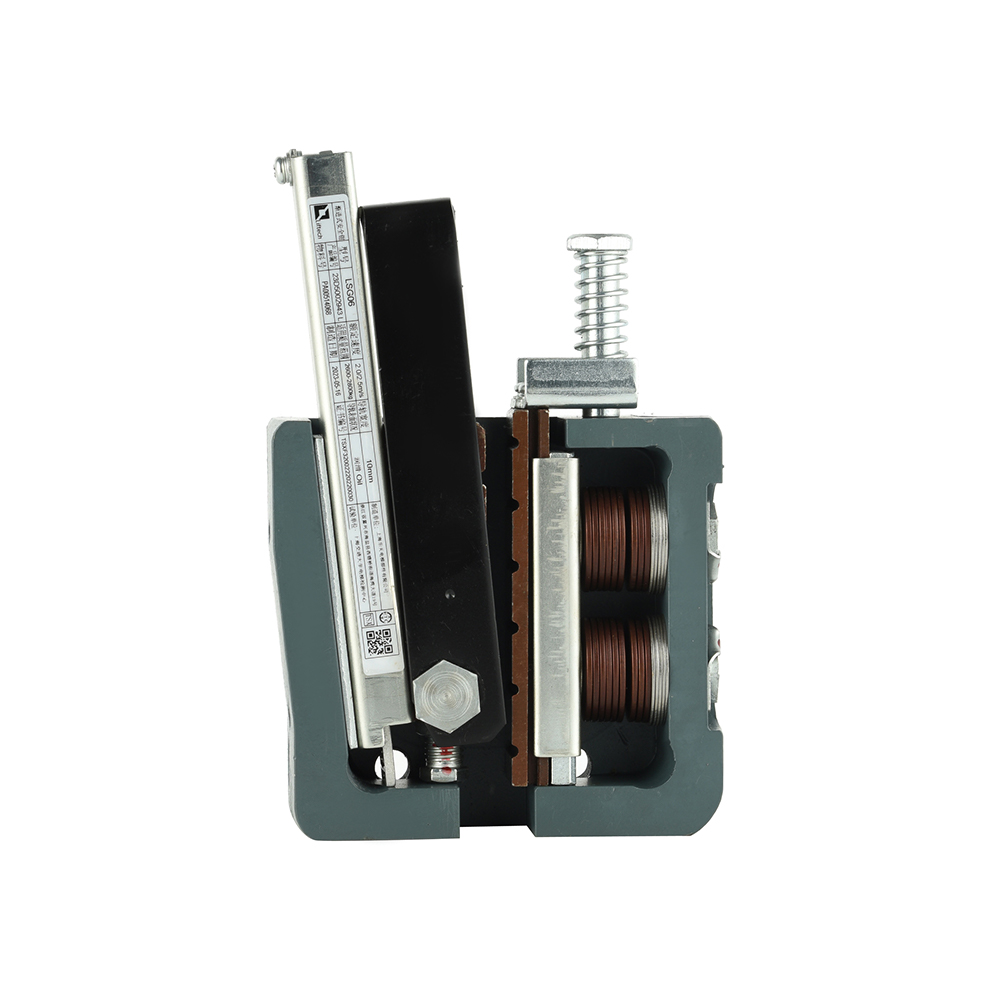
Instantaneous safety gears achieve full braking force almost immediately upon activation, resulting in a very short stopping distance but high deceleration forces. Progressive (or flexible) safety gears incorporate an energy-absorbing element-such as a spring, elastomer, or hydraulic damper-that modulates the braking force, extending the stopping distance and reducing deceleration.
| Parameter | Instantaneous Safety Gear | Progressive Safety Gear |
|---|---|---|
| Braking Action | Immediate full-force application | Gradual force buildup with modulation |
| Deceleration Profile | High peak deceleration (typically >2.5g) | Controlled deceleration (typically ≤1.0g) |
| Stopping Distance | Very short (millimeters to centimeters) | Longer (centimeters to decimeters) |
| Energy Absorption | Via wedge/roller deformation of rail | Via integrated spring/hydraulic elements |
| Typical Applications | Low-speed freight elevators, hydraulic elevators | High-speed passenger elevators |
Application Scenarios: When Progressive Outperforms Instantaneous
High-Rise Passenger Elevators: Progressive gears provide smoother deceleration, preventing passenger injury and discomfort during emergency stops from high speeds.
Machinery Spaces: Progressive gears reduce impact forces transmitted to the building structure.
Overspeed Governor Integration: Progressive gears require precise synchronization with governor tripping speeds to ensure proper force modulation.
EN81 Compliance Requirements for Each Safety Gear Type
EN81-20 mandates specific performance criteria: instantaneous gears must demonstrate stopping distances within defined limits based on tripping speed, while progressive gears must maintain average deceleration between 0.2g and 1.0g and peak deceleration below 2.5g. Type testing according to EN81-50 is required for all safety gears before market introduction.
Elevator Buffer Calculation Formula EN81: Ensuring Accurate Stopping Performance
Buffers are the final safety component in the event of car or counterweight overtravel. Proper elevator buffer calculation formula EN81 application ensures that kinetic energy is safely dissipated without damaging the structure or injuring occupants.
Energy Dissipation Principles for Polyurethane vs. Hydraulic Buffers
Buffers operate on two primary principles: energy storage (spring/polyurethane) and energy dissipation (hydraulic). Polyurethane buffers store energy during compression and release it during rebound, making them suitable for low-speed applications. Hydraulic buffers dissipate energy as heat through fluid displacement, providing smooth deceleration ideal for higher speeds.
| Parameter | Polyurethane Buffer (Energy Storage) | Hydraulic Buffer (Energy Dissipation) |
|---|---|---|
| Operating Principle | Elastic compression of polymer | Fluid displacement through orifices |
| Speed Range | ≤1.0 m/s (typical) | Up to 10 m/s+ |
| Rebound Characteristic | Significant rebound (requires restraint) | Minimal rebound (controlled return) |
| Temperature Sensitivity | Moderate (polymer stiffness varies) | Low (with proper fluid selection) |
Step-by-Step Calculation Methodology per EN81-20 Standards
Step 1: Determine rated speed (v) and mass (m) of the car plus rated load (for car buffers) or counterweight mass (for counterweight buffers).
Step 2: Calculate required stroke (s) for hydraulic buffers: s ≥ v² / (2 × a) where a is deceleration (typically ≤ 1.0g). EN81-20 mandates minimum stroke of 65 mm and maximum deceleration of 1.0g.
Step 3: For polyurethane buffers, verify that the buffer can absorb energy E = m × g × h where h is free-fall height corresponding to 115% of rated speed.
Step 4: Verify buffer selection against type test certification data per EN81-50.
Stroke Distance and Deceleration Rate Verification
Field verification requires measuring buffer stroke under load and confirming that deceleration during full compression tests remains within certified limits. Hydraulic buffers must be checked for fluid level and orifice condition annually.
Governor Overspeed Switch Testing Procedure: Maintaining Critical Safety Functions
The overspeed governor is the trigger mechanism for the entire safety chain. A systematic governor overspeed switch testing procedure ensures that both the mechanical tripping and electrical switching functions operate reliably.
Mechanical Trip Speed Calibration Methods
Governor trip speeds are set during manufacturing and must be verified periodically. Testing involves rotating the governor sheave at gradually increasing speed until mechanical tripping occurs, measured with a calibrated tachometer. EN81-20 requires the electrical overspeed switch to trip at a speed not exceeding 90% of the mechanical safety gear tripping speed.
Electrical Switch Continuity and Response Time Testing
Continuity Verification: Measure contact resistance across normally closed (NC) safety circuit contacts; resistance should be <0.1Ω.
Response Time: Using an oscilloscope or high-speed data logger, measure the interval between switch actuation and circuit interruption; should be <20ms for reliable safety circuit performance.
Switch Rating Verification: Confirm that switches are rated for the electrical load (typically 250V AC/DC, 2-5A) and that arc suppression (if required) is functional.
Periodic Inspection Intervals and Documentation Requirements
ASME A17.1 and EN81 require annual testing of governors, with detailed records maintained for each test including trip speeds, switch operation status, and any adjustments made. Five-year full load tests may be required depending on jurisdiction.
Elevator Door Interlock Monitoring System: Preventing Unsafe Door Operations
Door interlocks are the most frequently cycled safety components in any elevator system. A robust elevator door interlock monitoring system ensures that the car cannot move unless all hoistway doors and the car door are positively locked.
Contact vs. Contactless Monitoring Technologies
Traditional interlock monitoring relies on mechanical contacts that close when the lock mechanism is fully engaged. Contactless systems use magnetic or inductive proximity sensors to detect lock position without physical contact, offering advantages in wear reduction and contamination resistance.
| Technology | Operating Principle | Advantages | Limitations |
|---|---|---|---|
| Mechanical Contact (Microswitch) | Physical actuator depresses switch plunger when locked | Simple, proven technology, low cost | Contact wear, susceptibility to misalignment, contamination sensitivity |
| Magnetic Proximity (Reed/MR) | Magnetic field from lock mechanism activates sealed switch | No physical contact, sealed against contaminants | Magnet strength degradation over time, temperature sensitivity |
| Inductive Proximity | Metal target detected by electromagnetic field | Solid-state, high reliability, fast response | Higher cost, requires metal target and proper alignment |
Fault Detection and Diagnostic Capabilities
Modern monitoring systems include diagnostic features such as:
Open circuit detection for wiring faults
Stuck contact detection (monitoring cycle times and expected states)
Partial engagement detection (monitoring intermediate positions where applicable)
Remote monitoring interface for building management systems
Integration with Controller Safety Circuits
Interlock status must be integrated into the safety chain, typically through series-connected contacts or safety PLC inputs. EN81-20 requires that interlock monitoring be "positive opening" (mechanically forced contacts) for mechanical switches, or achieve equivalent safety integrity level (SIL) for electronic monitoring systems.
ASME A17.1 Elevator Safety Component Requirements: Navigating North American Standards
For projects in North America, compliance with ASME A17.1 elevator safety component requirements is mandatory. This standard, also known as the Safety Code for Elevators and Escalators, defines design, testing, and maintenance parameters for all safety components.
Key Differences Between ASME A17.1 and EN81 Standards
While both standards aim for equivalent safety outcomes, technical requirements differ in several areas:
| Aspect | ASME A17.1 | EN81-20/50 |
|---|---|---|
| Safety Gear Application | Requires safety gears for all traction elevators; specific requirements for instantaneous vs. progressive | Similar scope but different test load requirements and calculation methods |
| Buffer Stroke | Hydraulic buffer stroke = v² / (2 × 0.6g) (0.6g deceleration) | Hydraulic buffer stroke = v² / (2 × 1.0g) maximum |
| Door Interlock Monitoring | Requires electrical contacts with positive opening or equivalent electronic monitoring with SIL rating | Similar but with different SIL requirements and testing protocols |
| Governor Testing | Annual operational test; five-year full load test | Annual visual inspection; periodic trip speed verification |
Certification and Marking Requirements for Components
ASME A17.1 requires that all safety components bear permanent markings including manufacturer identification, model/serial number, rated speed/load/capacity, and certification reference. Components must be listed or labeled by an accredited certification organization.
Field Testing and Acceptance Criteria
New installations require comprehensive testing of all safety components under load, with documented results submitted to authorities having jurisdiction. Acceptance criteria include specified deceleration limits, stopping distances, and functional verification of all interlocks and switches.
Frequently Asked Questions About Elevator Safety Components
How often should elevator safety components be inspected?
ASME A17.1 and EN81 require monthly visual inspections of critical components (governor, safety gears, buffers, interlocks) by trained maintenance personnel, with annual comprehensive testing including governor trip speed verification and safety gear functionality under no-load or light-load conditions. Full-load testing of safety gears and governors is typically required every five years.
What is the typical lifespan of safety gear and buffers?
With proper maintenance, safety gears and buffers can last 15-25 years. However, components must be replaced if they have been activated in an actual overspeed event, show signs of corrosion or mechanical damage, or fail periodic testing. Hydraulic buffers require fluid replacement every 3-5 years depending on operating conditions.
Can safety components be repaired, or must they be replaced?
Most safety components are considered safety-critical and must be replaced rather than repaired. Exceptions include hydraulic buffer seal replacement and governor switch replacement, provided these repairs are performed by the original manufacturer or an authorized facility using certified parts. Field repair of safety gear gripping surfaces or load-bearing structures is prohibited by all major standards.
How do I verify if a component meets ASME or EN standards?
Request the component's type test certificate from the manufacturer. For EN81 compliance, look for certification from a notified body (NB) confirming testing per EN81-50. For ASME A17.1 compliance, verify listing by an accredited certification organization such as UL or CSA. The certificate should specify rated speed, load capacity, and any application limitations.
What documentation is required for safety component traceability?
Complete traceability requires: manufacturer's declaration of conformity (DoC), type test certificate, material certifications for load-bearing components, serial number tracking for each component, installation and maintenance records, and test reports from all periodic inspections. This documentation must be maintained for the life of the equipment.
References
American Society of Mechanical Engineers. (2019). ASME A17.1-2019: Safety Code for Elevators and Escalators. New York, NY: ASME.
European Committee for Standardization. (2020). EN 81-20:2020: Safety rules for the construction and installation of lifts - Lifts for the transport of persons and goods - Part 20: Passenger and goods passenger lifts. Brussels: CEN.
European Committee for Standardization. (2020). EN 81-50:2020: Safety rules for the construction and installation of lifts - Examinations and tests - Part 50: Design rules, calculations, examinations and tests of lift components. Brussels: CEN.
International Organization for Standardization. (2015). ISO 8100-1:2015: Lifts for the transport of persons and goods - Part 1: Safety rules for the construction and installation of passenger and goods passenger lifts. Geneva: ISO.
Elevator World, Inc. (2021). Elevator Safety Components: Design, Testing and Maintenance Handbook. Mobile, AL: Elevator World Publications.
Liftinstituut. (2022). Type Testing of Safety Gears According to EN 81-20/50: Technical Guidelines. Amsterdam: Liftinstituut.
Underwriters Laboratories. (2020). UL 104: Standard for Elevator Door Locking Devices. Northbrook, IL: UL.
International Union of Elevator Constructors. (2021). Safety Component Inspection and Maintenance Guidelines. Washington, DC: IUEC.